Track progress, take quizzes and save notes on this lesson.

Free forever · no card needed

Start free
Intermediate

Boolean Logic: Gates and Truth Tables

3.4.2 Boolean logic

Aligned to the AQA 8525 specification

Level
Intermediate
Reading time
7 min
Published
3 June 2026
Updated
1 July 2026
On this page
  1. 1.Logic Gates: Binary Decisions
  2. 2.The NOT Gate
  3. 3.AND and OR Gates
  4. 4.XOR: Exclusive OR
  5. 5.Boolean Expressions
  6. 6.Logic Circuits with Three Inputs
  7. 7.Common Exam Mistakes

Key takeaways

  • A logic gate takes one or more binary inputs (0 or 1) and produces a single binary output by a fixed rule; AQA 8525 requires only NOT, AND, OR and XOR, and excludes NAND and NOR.
  • AND outputs 1 only when all inputs are 1; OR outputs 1 when at least one input is 1; XOR outputs 1 only when its two inputs differ.
  • OR and XOR differ in exactly one row: when both inputs are 1, OR gives 1 but XOR gives 0.
  • A logic circuit with n inputs has exactly 2^n rows in its truth table: 1 input gives 2 rows, 2 inputs give 4, 3 inputs give 8.
  • In Boolean expressions AND (.) has higher precedence than OR (+), so A.B + C means (A.B) + C, not A.(B + C).

Logic Gates: Binary Decisions

A logic gate is a circuit component that takes one or more binary inputs (0 or 1) and produces a single binary output according to a fixed rule. Digital computers are built from billions of these gates.

The output of each gate is determined entirely by its inputs — there is no analogue gradation. Logic gates are the physical implementation of Boolean algebra, a mathematical system where values are either true (1) or false (0).

AQA 8525 requires knowledge of four gates:

GateInputsCore rule
NOT1Inverts the input
AND2 or moreOutput is 1 only if all inputs are 1
OR2 or moreOutput is 1 if at least one input is 1
XOR2Output is 1 if inputs are different

NAND and NOR gates are explicitly excluded from AQA 8525. Do not use them in answers unless the question supplies them.

Logic gates underpin all digital processing — from the arithmetic logic unit (ALU) inside a CPU to the condition checks in every if statement.

The NOT Gate

The NOT gate (also called an inverter) takes one input and produces its opposite. If the input is 1, the output is 0; if the input is 0, the output is 1.

Boolean notation: (A with an overbar, read "NOT A")

Truth table:

A (NOT A)
01
10

The NOT gate is the only single-input gate in AQA 8525. The circuit symbol is a triangle pointing right with a small circle (bubble) at the output.

Worked example — evaluate for both input values:

  • A = 0 → NOT gate inverts → output = 1
  • A = 1 → NOT gate inverts → output = 0

A truth table for a single-input gate always has exactly 2 rows ( input combinations). For 2 inputs: 4 rows. For 3 inputs: 8 rows.

The overbar in Boolean algebra () means "the complement of A". It always produces the opposite of A's current value.

AND and OR Gates

AND gate — output is 1 only when all inputs are 1. If any input is 0, the output is 0.

OR gate — output is 1 when at least one input is 1. Output is 0 only when all inputs are 0.

Boolean notation:

  • AND: (written A.B)
  • OR: (written A+B)

Truth tables (two inputs):

ABA.B (AND)A+B (OR)
0000
0101
1001
1111

AND produces a 1 in only one row (both inputs 1). OR produces a 1 in three rows (anything except both 0).

Worked example — evaluate where A = 1, B = 0, C = 1:

  1. = 1 AND 0 = 0
  2. = NOT(1) = 0
  3. = 0 OR 0 = 0 → final output = 0

AND is the stricter gate — all inputs must be 1. OR is more permissive — just one 1 is enough.

XOR: Exclusive OR

XOR (Exclusive OR) outputs 1 when its inputs are different — one is 0 and the other is 1. When both inputs are the same (both 0 or both 1), the output is 0.

Boolean notation:

Truth table:

AB (XOR)
000
011
101
110

XOR differs from OR in exactly one row: when A = 1 and B = 1, OR outputs 1 but XOR outputs 0.

Worked example — evaluate all four input combinations for :

  • 0 ⊕ 0 = 0 (same → 0)
  • 0 ⊕ 1 = 1 (different → 1)
  • 1 ⊕ 0 = 1 (different → 1)
  • 1 ⊕ 1 = 0 (same → 0)

XOR is used in binary addition (1 + 1 produces a sum bit of 0, which is the XOR of the two inputs), and in simple data checksums and encryption operations.

Mnemonics for XOR: "one but not both". The output is 1 only when exactly one input is 1.

Worth saving these ideas?

Turn what you've read into instant revision cards. Free to get started.

Make flashcards

Boolean Expressions

A Boolean expression describes the output of a logic circuit using algebraic notation. The four symbols used in AQA 8525 are:

OperationSymbolExample expression
AND.
OR+
XOR
NOToverbar

Evaluation order: . (AND) has higher precedence than + (OR), just as multiplication has higher precedence than addition. So means , not . When the intended order is non-standard, add brackets.

Reading a Boolean expression: evaluate inner operations first, then outer.

Worked example — evaluate where A = 1, B = 1, C = 0:

  1. = NOT(0) = 1
  2. = 1 AND 1 = 1
  3. = 1 OR 1 = 1 → output = 1

Writing an expression from a circuit: name each gate's output using the correct symbol, working left to right from inputs to final output.

  • Gate 1: AND(A, B) → output is
  • Gate 2: OR(, C) → final output is

Logic Circuits with Three Inputs

A logic circuit connects gates so the output of one feeds as input into another. For a circuit with three inputs, the truth table has rows.

Worked example — circuit: Gate 1 is AND(A, B); Gate 2 is NOT(C); Gate 3 is OR(Gate 1, Gate 2).
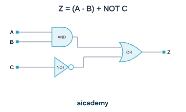
Z = (A · B) + NOT CABCANDNOTORZ

Boolean expression for output Z:

Complete truth table:

ABC
000011
001000
010011
011000
100011
101000
110111
111101

Reading the result: Z = 1 whenever C = 0 (because = 1) or when both A = 1 and B = 1. Z = 0 only when C = 1 and at least one of A or B is 0.

Add intermediate columns for each gate output (P, Q above). Building the table one gate at a time eliminates errors from trying to evaluate the whole expression at once.

Common Exam Mistakes

1. Confusing OR and XOR

OR outputs 1 when one or both inputs are 1. XOR outputs 1 only when exactly one input is 1. When A = 1 and B = 1: OR gives 1, XOR gives 0. This single row distinguishes the two gates.

2. Using NAND or NOR gates

AQA 8525 explicitly excludes NAND and NOR. If a question asks you to construct a logic circuit or Boolean expression, use only NOT, AND, OR, and XOR.

3. Wrong number of rows in the truth table

A circuit with inputs has exactly rows. Two inputs → 4 rows. Three inputs → 8 rows. Omitting rows or adding extras both lose marks.

4. Misreading the scope of the overbar

The overbar means NOT. Apply it to exactly the part of the expression it covers. If it covers A, it means NOT A. If it covers a bracketed expression, work out the expression first, then invert the result. AQA excludes NAND and NOR as standalone gate symbols, but NOT can still be used as part of a circuit.

5. Precedence errors in Boolean expressions

evaluates as , not . The two expressions produce different outputs. When tracing through an expression, resolve . (AND) operations before + (OR) operations.

Key terms

Logic gate
A circuit component that takes one or more binary inputs and produces a single binary output according to a fixed rule.
Boolean algebra
A mathematical system where values are either true (1) or false (0), physically implemented by logic gates.
NOT gate
A single-input gate, also called an inverter, that outputs the opposite of its input; written as A with an overbar.
AND gate
A gate whose output is 1 only when all of its inputs are 1; written A.B.
OR gate
A gate whose output is 1 when at least one input is 1, and 0 only when all inputs are 0; written A+B.
XOR gate
An exclusive OR gate whose output is 1 only when its two inputs are different; written A ⊕ B.
Truth table
A table listing every possible combination of inputs and the resulting output for a gate or circuit.
Boolean expression
An algebraic description of a logic circuit's output using the symbols for AND, OR, XOR and NOT.
Logic circuit
A connection of gates in which the output of one gate can feed as an input into another.

Frequently asked questions

OR outputs 1 when at least one input is 1, including when both are 1. XOR outputs 1 only when the inputs are different, so when both inputs are 1 OR gives 1 but XOR gives 0. This single row is what distinguishes the two gates.

AQA 8525 requires four gates: NOT, AND, OR and XOR. NAND and NOR are explicitly excluded, so you should not use them in answers unless a question supplies them.

A circuit with n inputs has exactly 2^n rows. One input gives 2 rows, two inputs give 4 rows, and three inputs give 8 rows. Omitting or adding rows both lose marks.

Generate revision on any topic you study

Type any topic you're studying and Aicademy generates a complete lesson, quiz, and flashcard set, personalised to your level.

Lessons on anything

Structured, level-matched lessons on any topic you study

Practice quizzes

Find out what you actually know before the exam does

Flashcard sets

Lock in key concepts with instant revision cards

Ask Aica

Stuck on something? Get a clear explanation, any time

Prev

Software Classification: System Software and Applications

Next

Programming Languages and Translators

Related lessons

Top students don’t revise more. They revise what counts.

Start revising free

Free to start. No card needed.