Track progress, take quizzes and save notes on this lesson.

Free forever · no card needed

Start free
Intermediate

Boolean Logic

2.4.1 Boolean logic

Aligned to the OCR J277 specification

Level
Intermediate
Reading time
6 min
Published
11 June 2026
Updated
1 July 2026
On this page
  1. 1.Boolean Values and Logic Gates
  2. 2.The AND Gate
  3. 3.The OR Gate
  4. 4.The NOT Gate
  5. 5.Combined Logic Diagrams
  6. 6.Applying Logic to Problems
  7. 7.Common Exam Mistakes

Key takeaways

  • The AND gate outputs 1 only when both inputs are 1; the OR gate outputs 1 when at least one input is 1; the NOT gate inverts a single input.
  • OCR J277 requires AND, OR, and NOT only - XOR, NAND, and NOR are outside the scope of this specification.
  • For n inputs, a truth table has 2^n rows - list inputs in binary counting order (00, 01, 10, 11) to guarantee all combinations are covered.
  • When evaluating a combined logic diagram, add one intermediate column per gate and evaluate left to right, one gate at a time - never try to skip steps.

Boolean Values and Logic Gates

Boolean logic describes how true/false values combine. Computers use Boolean logic at every level — from transistors in a processor to IF conditions in code. OCR J277 requires knowledge of three logic gates: AND, OR, and NOT.

Each gate takes one or two binary inputs (0 = False, 1 = True) and produces one binary output.

GateSymbol nameInputsOutput is 1 when...
ANDConjunctionA, BBoth A and B are 1
ORDisjunctionA, BAt least one of A or B is 1
NOTNegationAA is 0 (inverts the input)

OCR J277 requires AND, OR, and NOT only. XOR, NAND, and NOR are not in the scope of this specification.

Alternative notations accepted in the OCR exam:

  • 1/0 may be written as T/F (True/False)
  • OR may be written as V (from the Latin vel)
  • NOT A may be written as Ā (A with an overbar)

The AND Gate

The AND gate outputs 1 only when both inputs are 1. If either input is 0, the output is 0.

Real-world analogy: a security door that requires both a keycard AND a PIN to open.

Truth table for AND:

ABA AND B
000
010
100
111

Only the last row outputs 1. Out of 4 combinations, AND outputs 1 for exactly 1.

AND in a logic diagram: the AND gate symbol is a D-shape with a flat back edge. Two input lines enter on the left; one output line exits on the right.

AND in programming:

age = 20
has_id = True
if age >= 18 and has_id:
    print("Entry permitted")

Both conditions must be True for the output to be True — exactly like the AND gate.

The OR Gate

The OR gate outputs 1 when at least one input is 1. It outputs 0 only when both inputs are 0.

Real-world analogy: a burglar alarm that triggers if the front door OR the back door is opened.

Truth table for OR:

ABA OR B
000
011
101
111

Three out of four combinations output 1. OR outputs 0 only when both inputs are 0.

OR in a logic diagram: the OR gate symbol is a curved D-shape with a concave back edge. Two inputs on the left; one output on the right.

OR in programming:

subject = "Maths"
if subject == "Maths" or subject == "Science":
    print("STEM subject")

The output is True if the student takes Maths or Science (or both).

The NOT Gate

The NOT gate (inverter) takes a single input and produces the opposite output: 1 becomes 0, and 0 becomes 1.

Real-world analogy: a light that is ON when the switch is NOT pressed.

Truth table for NOT:

ANOT A
01
10

NOT in a logic diagram: a triangle (buffer) with a small circle (bubble) on the output line. The bubble indicates inversion.

NOT in programming:

game_over = False
while not game_over:
    playTurn()

The loop continues while game_over is NOT True.

NOT is the only gate with a single input. AND and OR each take exactly two inputs. In a combined diagram, NOT is often placed after another gate to invert its output.

Studying this for an exam?

Generate a personalised learning path for this subject. Free to get started.

Create a learning path

Combined Logic Diagrams

A logic diagram can combine multiple gates to represent complex Boolean expressions. Evaluate from inputs to output, left to right, one gate at a time.

Worked example — evaluate the output of: A AND B, then NOT the result.
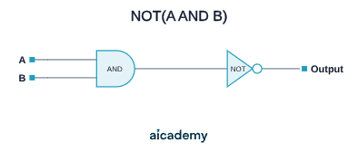
NOT(A AND B)ABANDNOTOutput

Truth table for NOT(A AND B):

ABA AND BNOT(A AND B)
0001
0101
1001
1110

Step-by-step for A=1, B=1: AND gate → 1 AND 1 = 1; NOT gate → NOT 1 = 0. Output = 0.

Worked example — evaluate: (A OR B) AND (NOT A)
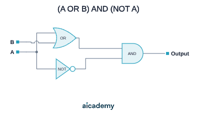
(A OR B) AND (NOT A)ABORNOTANDOutput
ABA OR BNOT A(A OR B) AND (NOT A)
00010 AND 1 = 0
01111 AND 1 = 1
10101 AND 0 = 0
11101 AND 0 = 0

For each row: compute all intermediate values first, then apply the final gate.

Applying Logic to Problems

Boolean expressions appear in programming conditions and in exam diagram questions. Being able to convert between a diagram, a truth table, and a written expression is the key skill.

From description to truth table — a sensor system activates an alarm (output = 1) when there is motion (M=1) OR it is dark (D=1) AND an override is NOT active (O=0).

Expression: Output = M OR (D AND NOT O)

MDONOT OD AND NOT OM OR (D AND NOT O)
000100
001000
010111
011000
100101
101001
110111
111001

For 3 inputs there are rows. Work column by column from left to right.

Common Exam Mistakes

1. Confusing AND and OR output rules

AND outputs 1 only when both inputs are 1 — it is the stricter gate.
OR outputs 1 when any input is 1 — it only outputs 0 when both inputs are 0.
Swapping these is the most common error in truth table questions.

2. Missing rows in a truth table

For 2 inputs: 4 rows (). For 3 inputs: 8 rows (). List inputs in binary counting order (00, 01, 10, 11) to guarantee all combinations are covered.

3. Forgetting to add intermediate columns in combined gates

When a diagram has multiple gates, add a column for each gate's output. Trying to evaluate the final output in one step causes errors. Always work gate by gate.

4. Applying NOT incorrectly

NOT inverts a single value: NOT 1 = 0, NOT 0 = 1. It does not apply to the entire expression unless brackets indicate otherwise. NOT(A AND B) is different from (NOT A) AND (NOT B).

MistakeCorrection
"AND outputs 1 when any input is 1"That describes OR; AND requires both inputs to be 1
Truth table with 3 rows for 2 inputs2 inputs → = 4 rows; 3 inputs → = 8 rows
Skipping intermediate gate columnsAdd one column per gate; evaluate left to right

Key terms

Boolean logic
A system of logic based on true/false (1/0) values, used at every level of computing from transistors to programming conditions.
AND gate
A logic gate that outputs 1 only when both of its two inputs are 1; outputs 0 in all other cases.
OR gate
A logic gate that outputs 1 when at least one of its two inputs is 1; outputs 0 only when both inputs are 0.
NOT gate
A logic gate (inverter) with a single input that outputs the opposite value: NOT 1 = 0 and NOT 0 = 1.
Truth table
A table listing all possible combinations of binary inputs and the corresponding output for a logic expression or gate.
Logic diagram
A diagram that shows logic gates connected by lines to represent a Boolean expression visually.
Boolean expression
A written formula combining inputs and operations (AND, OR, NOT) that evaluates to a single true/false output, e.g. NOT(A AND B).
Intermediate column
An extra column added to a truth table to record the output of each gate in a combined diagram before calculating the final result.

Frequently asked questions

AND outputs 1 only when both inputs are 1 - it is the stricter gate. OR outputs 1 when at least one input is 1, outputting 0 only when both inputs are 0. Swapping these is the most common truth table error.

For 2 inputs you need 2^2 = 4 rows. For 3 inputs you need 2^3 = 8 rows. List inputs in binary counting order starting from 00...0 to make sure every combination is included.

Work left to right, evaluating one gate at a time. Add an intermediate column for each gate's output. Evaluate the intermediate values first, then use those as inputs for the next gate. Never jump straight to the final output.

Generate revision on any topic you study

Type any topic you're studying and Aicademy generates a complete lesson, quiz, and flashcard set, personalised to your level.

Lessons on anything

Structured, level-matched lessons on any topic you study

Practice quizzes

Find out what you actually know before the exam does

Flashcard sets

Lock in key concepts with instant revision cards

Ask Aica

Stuck on something? Get a clear explanation, any time

Prev

Testing Programs

Next

Programming Languages and IDEs

Related lessons

Top students don’t revise more. They revise what counts.

Start revising free

Free to start. No card needed.

Boolean Logic: OCR GCSE Computer Science | Aicademy