Track progress, take quizzes and save notes on this lesson.

Free forever · no card needed

Start free
Advanced

Resistors and Circuit Components

4.2.1.4 Resistors and I–V characteristics (including Required practical 4)

Aligned to the AQA 8463 specification

Level
Advanced
Reading time
7 min
Published
2 July 2026
On this page
  1. 1.Ohmic Conductors: Constant Resistance
  2. 2.Reading I–V Characteristics
  3. 3.The Filament Lamp: Resistance Rises with Heat
  4. 4.Diodes, Thermistors and LDRs
  5. 5.Required Practical 4: I–V Characteristics
  6. 6.Common Exam Mistakes

Key takeaways

  • An ohmic conductor at constant temperature has a constant resistance, so its I–V graph is a straight line through the origin and current is directly proportional to potential difference.
  • A filament lamp is non-ohmic: as current rises the filament heats up, its resistance increases, and its I–V graph curves (an S-shape through the origin).
  • A diode only lets current flow one way; its resistance is very high in the reverse direction, so its I–V graph shows current only for forward potential difference.
  • A thermistor's resistance decreases as temperature increases; an LDR's resistance decreases as light intensity increases.
  • Required practical 4 uses a circuit with a variable resistor to obtain the I–V characteristics of a resistor, a filament lamp and a diode.

Ohmic Conductors: Constant Resistance

An ohmic conductor is a component whose resistance stays constant as long as its temperature does not change. A fixed resistor at constant temperature is the standard example.

Because the resistance is fixed, rearranging shows that current is directly proportional to potential difference:

Double the potential difference and the current doubles. On a graph of current (-axis) against potential difference (-axis), this gives a straight line through the origin.

The equation is used throughout this topic. You must recall and apply it; it is not on the Physics equation sheet.

The gradient of a straight I–V line tells you about the resistance: a steeper line means a smaller resistance (more current per volt), a shallower line means a larger resistance.

Reading I–V Characteristics

An I–V characteristic is a graph of current against potential difference for a component. Its shape reveals how the component's resistance behaves. There are three shapes you should be able to recognise and interpret.

ComponentShape of I–V graphWhat it tells you
Fixed resistor (ohmic)Straight line through the originResistance is constant
Filament lampS-shaped curve through the originResistance increases as it heats up
DiodeFlat (zero current) for reverse pd, then rising for forward pdConducts one way only

The key skill is judging linear versus non-linear: a straight line means constant resistance (ohmic); any curve means the resistance is changing, so the component is non-ohmic.

For a curved graph, resistance at any point is found from the values there using , not from the gradient (the gradient only gives resistance directly for a straight line through the origin).

The Filament Lamp: Resistance Rises with Heat

A filament lamp contains a thin coil of metal wire, the filament, that glows white-hot when current flows.

As the current increases, the filament gets hotter. In a metal, a higher temperature makes the atoms vibrate more, which obstructs the flowing electrons, so the resistance increases.

This is why the filament lamp is non-ohmic. Its I–V graph is an S-shaped curve through the origin: near the middle the line is steep (low resistance while cool), but as the potential difference and current grow the line bends over, because the rising resistance means each extra volt adds less current.

A filament lamp's resistance increases as its temperature increases. This makes the graph curve; it is not a straight line.

The curve is symmetrical about the origin: reversing the potential difference reverses the current in the same way, because the filament heats up regardless of current direction.

Diodes, Thermistors and LDRs

Three more components have a resistance that is not constant.

Diode. A diode lets current flow in one direction only. It has a very high resistance in the reverse direction, so almost no current flows that way. Its I–V graph is flat (zero current) for reverse potential difference, then rises steeply once the forward potential difference is large enough. Diodes are used to protect circuits and to convert alternating current to direct current.

Thermistor. A thermistor's resistance decreases as temperature increases. When it warms up, more current can flow. This makes it ideal for temperature sensing, for example in a thermostat that switches heating on when a room gets cold.

LDR (light-dependent resistor). An LDR's resistance decreases as light intensity increases. In bright light it has low resistance; in the dark its resistance is high. This is used in circuits that switch lights on automatically in the dark, such as street lighting.

ComponentResistance changes with…EffectTypical use
ThermistorTemperatureResistance falls as temperature risesThermostat
LDRLight intensityResistance falls as light risesAutomatic outdoor lighting
DiodeDirection of pdVery high resistance in reverseRectifying / protecting circuits

Want more lessons like this one?

Generate lessons on anything you study. Free account, no card needed.

Start generating

Required Practical 4: I–V Characteristics

Aim: obtain the I–V characteristics of a fixed resistor, a filament lamp and a diode at constant temperature.

Apparatus: the test component, a cell or power supply, an ammeter (in series), a voltmeter (in parallel across the component), a variable resistor and connecting leads. The circuit below shows the arrangement for the resistor.
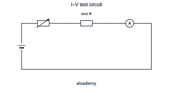
The voltmeter is then connected in parallel across the test component.

Method:

  1. Build the circuit with the ammeter in series and the voltmeter in parallel across the component under test.
  2. Adjust the variable resistor to change the current, and record the current and the potential difference at each setting.
  3. Take several readings across a range of potential differences.
  4. Reverse the connections to the cell and repeat, so you get negative values of and too.
  5. Plot (y-axis) against (x-axis) and repeat the whole method for each component.
VariableTypeDetail
Potential difference (set by variable resistor)IndependentChanged at each reading
CurrentDependentMeasured with the ammeter
Temperature of the componentControlKeep readings brief so it stays constant

Why use a variable resistor: it lets you change the current without changing the component being tested, so you can plot many points on the same characteristic.

Expected results: the resistor gives a straight line through the origin; the filament lamp gives an S-shaped curve; the diode gives current only in the forward direction.

Common Exam Mistakes

1. Calling a filament lamp ohmic

A filament lamp is non-ohmic: its resistance rises as it heats, so its graph curves. Only a fixed resistor at constant temperature gives the straight line.

2. Mixing up thermistors and LDRs

A thermistor responds to temperature; an LDR responds to light. Both have resistance that falls as the input (heat or light) rises, but they sense different things.

3. Getting the diode graph the wrong way round

A diode conducts only when the potential difference is in the forward direction. In reverse its resistance is very high, so the current is essentially zero.

4. Reading resistance from the gradient of a curve

For a curve, work out resistance at a point using with the values at that point. The gradient only gives resistance directly for a straight line through the origin.

5. Forgetting to keep the temperature constant

If the component heats up during the test (especially the resistor), its resistance drifts and the line stops being straight. Take readings quickly and keep the current modest.

Key terms

Ohmic conductor
A component whose resistance stays constant at constant temperature, so current is directly proportional to potential difference.
I–V characteristic
A graph of current against potential difference for a component, used to show how its resistance behaves.
Filament lamp
A lamp with a thin metal wire (filament) that heats up and glows; its resistance rises as it gets hotter.
Diode
A component that lets current flow in one direction only, having very high resistance in the reverse direction.
Thermistor
A resistor whose resistance decreases as temperature increases.
Light-dependent resistor (LDR)
A resistor whose resistance decreases as light intensity increases.

Frequently asked questions

An ohmic conductor keeps a constant resistance at constant temperature, so its I–V graph is a straight line through the origin. A non-ohmic conductor, such as a filament lamp or diode, has a resistance that changes, so its I–V graph is curved.

As the current increases, the filament gets hotter. A hotter metal filament has a higher resistance, so the current increases less steeply for each extra volt. This gives a curved (S-shaped) I–V graph rather than a straight line.

A thermistor's resistance decreases as its temperature increases. This makes it useful in temperature-sensing circuits such as thermostats, where a change in temperature changes the current in the circuit.

Generate revision on any topic you study

Type any topic you're studying and Aicademy generates a complete lesson, quiz, and flashcard set, personalised to your level.

Lessons on anything

Structured, level-matched lessons on any topic you study

Practice quizzes

Find out what you actually know before the exam does

Flashcard sets

Lock in key concepts with instant revision cards

Ask Aica

Stuck on something? Get a clear explanation, any time

Prev

Resistance and Ohm's Law

Next

Series and Parallel Circuits

Related lessons

5 min

Lesson

Resistance and Ohm's Law

AQA GCSE Physics · AQA 8463

19 days ago

6 min

6 min

Top students don’t revise more. They revise what counts.

Start revising free

Free to start. No card needed.