Logic Gates to Circuits: Worked Practice

Aligned to the AQA 8525 specification
- Level
- Intermediate
- Reading time
- 6 min
- Published
- 9 June 2026
- Updated
- 16 August 2026
On this page
Key takeaways
- AQA 8525 uses only three logic gates: NOT flips its input, AND outputs 1 only if both inputs are 1, and OR outputs 1 if at least one input is 1.
- To trace a multi-gate circuit, work left to right, calculating and labelling the output of each gate before moving on to the next.
- A truth table for a multi-gate circuit needs one column per intermediate value, not just columns for the inputs and the final output.
- A two-input circuit always has exactly 4 rows and a three-input circuit always has exactly 8 rows, because the row count is 2 to the power of the number of inputs.
- NOT A AND B means (NOT A) AND B, with the NOT applying only to A; reading it as NOT (A AND B) gives a completely different truth table.
Tracing a Circuit Step by Step
When a circuit has more than one gate, work through it left to right — calculate the output of each gate before moving to the next.
Example circuit:
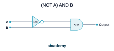
This circuit feeds A through a NOT gate first, then ANDs the result with B.
Inputs: A = 1, B = 0
| Step | Operation | Value |
|---|---|---|
| 1 | NOT A | NOT 1 = 0 |
| 2 | (NOT A) AND B | 0 AND 0 = 0 |
| Output | 0 |
Inputs: A = 0, B = 1
| Step | Operation | Value |
|---|---|---|
| 1 | NOT A | NOT 0 = 1 |
| 2 | (NOT A) AND B | 1 AND 1 = 1 |
| Output | 1 |
Always label intermediate values as you go. On an exam diagram, write the value on each wire after each gate — the examiner can see your working and may award method marks even if your final answer is wrong.
How much of this have you taken in?
Quiz yourself on this section, free, no card needed.
Boolean Expressions and Circuit Diagrams
AQA may give you a Boolean expression and ask you to draw or complete the circuit, or give you a circuit and ask you to write the expression.
Expression → Circuit:
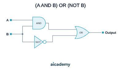
Expression: (A AND B) OR (NOT B)
Read it as a recipe:
- Feed A and B into an AND gate
- Feed B into a NOT gate
- Feed both outputs into an OR gate
Circuit → Expression:
Work left to right, naming each gate's output:
- Gate 1 (NOT on A): NOT A
- Gate 2 (AND on NOT A, and B): (NOT A) AND B
- If there were a further gate, continue chaining
The expression for the full circuit is: (NOT A) AND B
Key terms
- NOT gate
- A gate that flips its single input: 0 becomes 1 and 1 becomes 0.
- AND gate
- A gate whose output is 1 only if both of its inputs are 1.
- OR gate
- A gate whose output is 1 if at least one of its inputs is 1.
- Logic circuit
- Several logic gates connected together to produce an output from one or more inputs.
- Truth table
- A table listing every combination of inputs and the resulting output, with one row per combination.
- Intermediate value
- The output of a gate partway through a circuit, given its own column in a truth table.
- Boolean expression
- A written formula using AND, OR, and NOT that describes a logic circuit, such as (A AND B) OR (NOT B).
Frequently asked questions
A two-input circuit always has exactly 4 rows and a three-input circuit always has exactly 8 rows, because the number of rows is 2 to the power of the number of inputs. Never skip or duplicate rows, even if your gate logic is correct.
Work through the circuit left to right, calculating the output of each gate before moving to the next, and label the intermediate value on each wire as you go. Use a truth table with one column per intermediate value rather than trying to do it in one step.
No. NOT A AND B means (NOT A) AND B, so the NOT applies only to A. Reading it as NOT (A AND B) produces a completely different truth table. If in doubt, add brackets to make the order clear.
Generate revision on any topic you study
Type any topic you're studying and Aicademy generates a complete lesson, quiz, and flashcard set, personalised to your level.
Lessons on anything
Structured, level-matched lessons on any topic you study
Practice quizzes
Find out what you actually know before the exam does
Flashcard sets
Lock in key concepts with instant revision cards
Ask Aica
Stuck on something? Get a clear explanation, any time
Exam Technique and Command Words
Writing Exam-Style Programs
Related lessons
7 min
6 min