Logic Gates and Circuits

Aligned to the AQA 7517 specification
- Level
- Intermediate
- Reading time
- 6 min
- Published
- 13 June 2026
- Updated
- 16 August 2026
On this page
Key takeaways
- OR outputs 1 when at least one input is 1, while XOR outputs 1 only when the inputs are different, so XOR(1,1) = 0; the half adder Sum uses XOR, not OR.
- NAND is AND followed by NOT (output 0 only when both inputs are 1); NOR is OR followed by NOT (output 1 only when both inputs are 0).
- A half adder adds two single bits with Sum = A XOR B and Carry = A AND B; it is called half because it has no carry-in input and cannot chain for multi-bit addition.
- A full adder adds two bits plus a carry-in, producing a Sum and a carry-out, and can be chained (n full adders) to add two n-bit binary numbers.
- A D-type flip-flop stores one bit: output Q takes the value of D only on a rising clock edge and otherwise holds its previous value, making it the building block of sequential circuits.
Reading and Drawing Circuits
Logic gates are connected in circuits to implement more complex Boolean functions. Each gate's output can feed into another gate's input.
Example circuit — two gates in sequence:
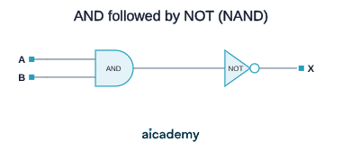
Boolean expression: — this is a NAND.
Completing a truth table for a circuit:
Circuit:
| A | B | C | A AND B | X = (A AND B) OR C |
|---|---|---|---|---|
| 0 | 0 | 0 | 0 | 0 |
| 0 | 0 | 1 | 0 | 1 |
| 0 | 1 | 0 | 0 | 0 |
| 0 | 1 | 1 | 0 | 1 |
| 1 | 0 | 0 | 0 | 0 |
| 1 | 0 | 1 | 0 | 1 |
| 1 | 1 | 0 | 1 | 1 |
| 1 | 1 | 1 | 1 | 1 |
Method: add intermediate columns for each gate's output, working left to right through the circuit. Never try to evaluate the whole expression in one column.
Studying this for an exam?
Generate a personalised learning path for this subject. Free to get started.
Key terms
- Logic gate
- A basic building block of digital circuits that takes one or more binary inputs and produces a single binary output according to a fixed logical rule.
- AND gate
- A gate whose output (A AND B) is 1 only when both inputs are 1.
- OR gate
- A gate whose output (A OR B) is 1 when at least one input is 1.
- XOR gate
- A gate whose output (A XOR B) is 1 only when the inputs are different.
- NAND gate
- An AND gate followed by NOT (NOT(A AND B)); its output is 0 only when both inputs are 1.
- NOR gate
- An OR gate followed by NOT (NOT(A OR B)); its output is 1 only when both inputs are 0.
- Half adder
- A circuit that adds two single bits, producing Sum = A XOR B and Carry = A AND B, with no carry-in input.
- Full adder
- A circuit that adds two bits plus a carry-in, producing a Sum and a carry-out, and can be chained for multi-bit addition.
- D-type flip-flop
- A memory element that stores one bit, where output Q takes the value of input D on a rising clock edge and otherwise holds its previous value.
- Sequential circuit
- A circuit, such as a register, counter, or memory cell, built from flip-flops that can remember and store information between clock cycles.
Frequently asked questions
OR outputs 1 when at least one input is 1, including when both are 1. XOR outputs 1 only when the inputs are different, so XOR(1,1) = 0, not 1. For the half adder Sum it is XOR, not OR.
A half adder adds two single bits A and B, producing Sum = A XOR B and Carry = A AND B, but has no carry-in. A full adder adds two bits plus a carry-in, producing a Sum and a carry-out, so it can be chained to add multi-bit binary numbers.
A D-type flip-flop has a Data input D and a Clock input CLK. Output Q takes the value of D only on a rising (low to high) edge of the clock, and between clock edges Q holds its previous value regardless of D, giving it state that persists.
Generate revision on any topic you study
Type any topic you're studying and Aicademy generates a complete lesson, quiz, and flashcard set, personalised to your level.
Lessons on anything
Structured, level-matched lessons on any topic you study
Practice quizzes
Find out what you actually know before the exam does
Flashcard sets
Lock in key concepts with instant revision cards
Ask Aica
Stuck on something? Get a clear explanation, any time
Programming Languages and Translators
Boolean Algebra
Related lessons
6 min
5 min
6 min
Processor Components and the Fetch-Execute Cycle
A-Level Computer Science · AQA 7517
4 months ago